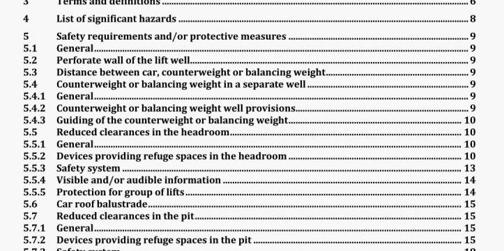
AS 1735.20-2020 pdf download.Lifts, escalators and moving walks
Part 20: Safety rules for the construction and installation of lifts — Lifts for the transport of persons and goods — New passenger and goods passenger lifts in existing building.
5.1 General
Lifts within the scope of this standard shall comply with the relevant safety requirements and/or protective measures of the following clauses where one or several requirements in EN 81-20:2014 cannot be fulfilled. In addition, the lift shall be designed according to the principles of EN ISO 12 100:2010 for relevant but not significant hazards, which are not dealt with by this standard.
5.2 Perforate wall of the lift well
The requirements for the well enclosure of EN 81-20:2014, 5.2.5.2 are complemented by the following:
Any existing well enclosure may be perforate provided that
a) EN ISO 13857:2008, 4.2.4.2 is fulfilled; and
b) a protective imperforate screen shall be provided around the landing door locking devices in order to prevent any manipulation of the locking devices by means of a rigid rod ft.30 m long.
NOTE National regulations for the preservation of historical buildings may require the retention of an existing perforate enclosure.
5.3 Distance between car, counterweight or balancing weight
The requirements of EN 81-20:20 14, 5.2.5.5.1 h) for this distance may be replaced by the following:
The car and its associated components shall be at a distance of at least 25 mm from the counterweight or balancing weight (if there is one) and its associated components.
To avoid any impact between the car (and its associated components) and the counterweight or balancing weight (and its associated components), in case of failure of normal guidance, emergency guidance on the car and counterweight shall be provided to maintain the car and the counterweight in their horizontal position.
5.4 Counterweight or balancing weight in a separate well
5.4.1 General
The counterweight or the balancing weight may be installed in a separate well from the car, provided that the configuration on site does not permit the installation of a lift having an available car area sufficient to fulfil the transport needs.
NOTE The standard covers only the installation of one counterweight (or balancing weight) in Its own well.
The following requirements shall be met.
c) the distance between inspection doors and equipment requiring maintenance or inspection shall not exceed 0,7 m;
d) where a safety gear is installed at the counterweight/balancing weight, inspection doors shall- provide access to be able to inspect and maintain the full travel of the counterweight/balancing weight;
e) stopping device(s) accessible on opening the inspection doors at both ends of the separate well shall be provided, In conformity with the requirements of EN 81-20:2014, 5.12.1.11;
1) electric socket outlets accessible on opening the inspection doors at both ends of the well shall be provided as defined in EN 8 1-20:2014. 5.10.7.2;
g) the separate well shall be exclusively used for the lift in compliance with EN 81-20:20 14, 5.2.1.2;
h) the separate well shall be provided with permanently installed electric lighting, giving an intensity of at least 50 lux on the equipment requiring maintenance/inspection;
I) means to switch the separate well lighting shall be provided on opening the inspection door at the lower end of the well.
5.4.3 Guiding of the counterweight or balancing weight
The requirements of EN 81-20:2014,5.7.1 are supplemented as follows:
When travelling in a separate well, the counterweight or the balancing weight may be guided by ropes or by the shape of the counterweight or the balancing weight and its well enclosure.
If the counterweight or balancing weight is resting on its buffers it shall be kept in a substantially upright position by the use of a small distance to the well enclosure or an emergency guiding. Provisions shall be made so as to avoid the counterweight or the balancing weight to rotate, e.g. by using equal number of left and right twisted suspension ropes.
Where its shape guides the counterweight or balancing weight, the enclosure of the well shall be continuous and flush without any protrusion from which the counterweight or the balancing weight can be blocked. The well enclosure shall be covered by durable material.
In case of ropes as guiding elements a minimum number of 4 ropes shall be used. Springs or weights shall tighten the ropes. The horizontal free distance between the counterweight or the balancing weight and the well enclosure shall be at least 50 mm if the enclosure of the well is continuous and flush otherwise It shall be increased by 2 mm for each meter of distance between the fixations of the ropes.
5.5 Reduced clearances in the headroom.AS 1735.20-2020 pdf download.Lifts, escalators and moving walks
Lifts, escalators and moving walks
